


How to Solid Axle Swap a 2001-2010 Chevy 2500 – Part 2: Chevy SAS Kit Installation
Part 2: Building and Welding the SAS Kit
Project SilverDuty: 2001-2010 Chevy 2500 SAS Build Overview
In Part 1, I removed the factory IFS and prepped the frame on this GMT800 Chevy 2500 solid axle swap. In Part 2, I install the main Chevy SAS kit components: frame plates, coil buckets, panhard mounts and bar, transmission crossmember mounts, axle placement for the Ford SuperDuty Dana 60, and custom radius arms.
This is part 2 of my Chevy 2500 solid axle swap build series:
In this guide:
- Frame Plates and Prep
- Chevy SAS Coil Buckets
- Panhard / Trackbar Mount
- Transmission Crossmember
- Axle Placement and Caster
- Radius Arms
- Panhard Bar
- Shocks, Bumpstops, Limiting Straps
- Final Notes
Quick Specs:
- Truck: 2001-2010 Chevy/GMC 2500/3500 GMT800 platform(IFS)
- Axle: 2005-2017 SuperDuty Dana 60
- This post covers: designing, cutting, and welding SAS kit brackets
- Tools: basic hand tools, cutting, grinding, and welding
- Skill level: experienced DIY; welding and cutting required
Missed the first step? Read Part 1: IFS removal and frame prep here.
Fabrication vs Buying a Kit
If you want to build your own Chevy 2500 solid axle swap from scratch, this guide and video will show you how I laid everything out, mocked it up, and welded it together. If you’d rather skip the measuring and bracket cutting, I also offer individual Chevy SAS brackets and a complete kit.
- You can build everything yourself using basic tools: tape measure, angle grinder, drill press, and welder.
- This requires layout, cutting brackets, mockup, and trial fitting. All prototypes in the video were built this way.
- If you want to skip the measuring and cutting, I offer the brackets individually or as a complete kit.
Photos throughout the guide are taken directly from my build video. This post contains affiliate links. If you purchase through them, I may earn a small commission at no extra cost to you.
If you want to see the full bracket mockup, fitment, and welding process, watch the Part 2 build video below.

Watch the full video above, then continue below for written notes, design details, and links to the parts used in this Chevy 2500 SAS build.
Tools Used for This Chevy SAS Build
Miller 180 – 220v mig welder
- Shop My Recommended Gear
Chevy SAS Frame Plates and Frame Prep

Frame Plates clamped in place ready for welding
On a GMT800 Chevy 2500 SAS swap, frame plates are the foundation for mounting coil buckets, crossmember brackets, and front suspension components.
After removing the factory IFS brackets in Part 1, the frame is left with large holes and uneven surfaces. Frame plates restore strength and create a clean mounting surface for coil buckets and suspension brackets.
Proper prep is critical for good welds. Use a wire wheel and flap discs to remove all paint and rust before welding.
The frame has a natural bend. Cutting a relief slot in the plate allows you to clamp, hammer, and form it to match the frame. A few good clamps make this much easier. Tack weld once everything is tight.
Design Notes
1/4″ plate steel
Pointed ends to reduce stress risers
Covers factory frame holes from IFS removal
Alignment notches cut to index coil buckets
Welding
Stitch weld in 2″ increments
Alternate sides to control heat
Avoid concentrating heat in one area
If you don’t want to design and cut these yourself, I offer pre-cut Chevy 2500 SAS frame plates here.
Chevy SAS Coil Buckets
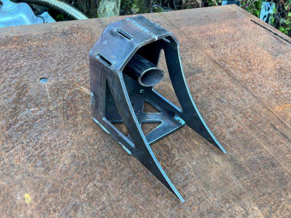
Coil Buckets welded up and ready to tack in place.

Coil Bucket tracked in place onto frame plate.
These Chevy SAS coil buckets are designed around 2005-2017 Ford F-250/F-350 coil springs and SuperDuty Dana 60 swap components. Installed at the factory reference points, they sit at roughly stock ride height.
They can be repositioned for:
+2″ lift
Construction
1/4″ plate steel
Lightening cutouts
Alignment tabs that index into frame plate notches
Proper bucket height determines ride height and shock travel, so mock-up with the axle in place before final welding.
I also offer Chevy SAS coil buckets individually or as part of the complete Chevy 2500 SAS kit.
Chevy SAS Panhard / Track Bar Mount
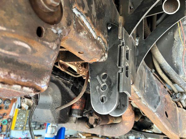
Panhard Bracket with adjustable holes.
The panhard bar keeps the axle centered side to side in a radius arm suspension. Clearance is tight around the SD60 differential.
Ideally, the panhard bar should be as close to horizontal as possible. This reduces side-to-side movement during suspension travel. Steeper angles will cause the axle to shift as it cycles.
The bracket is a three-piece design, spaced 2 5/8″ apart for a Johnny Joint or heim.
When welding the bracket, use a bolt and spacers to maintain correct width, then hold everything square with magnetic welding squares or clamps while tacking it together.
If you want to save time on layout and cutting, I also offer Chevy SAS panhard brackets for both the frame side and axle side.
Chevy SAS Transmission Crossmember
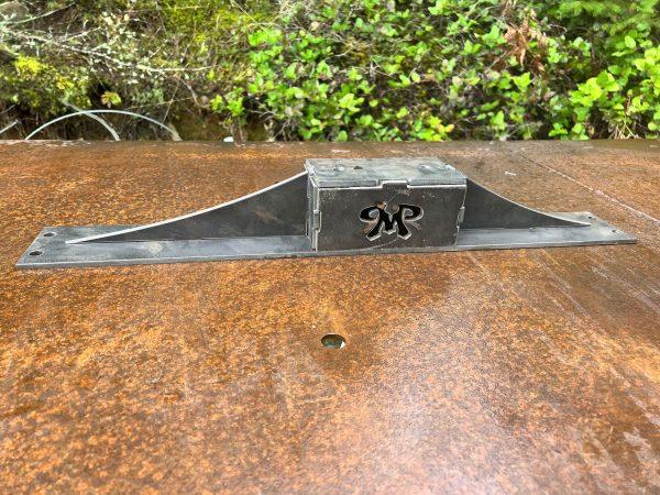
Chevy 2500 SAS Transmission Crossmember on bench ready for mockup.

Frame plates and cross member getting ready for welding.
The factory crossmember must be removed to allow proper axle placement and clearance. Make sure to support the transmission or transfer case prior to unbolting the crossmember. Do not allow the drivetrain to hang unsupported off the motor mounts.
Crossmember Removal
(4) 21mm bolts per side
(2) 15mm bolts at transmission mount
Once removed, the new frame plates get positioned on the frame using the old transmission cross member rear bolt as an alignment hole. Frame brackets get tacked into place on either side and then the transmission crossmember can be assembled in place and tacked together before removing and bench welding everything.
If you want to skip building this piece from scratch, I also offer a Chevy SAS transmission crossmember.
Axle Placement & Caster

Getting the axle lined up at drive height to measure radius arms.
Axle placement is one of the most important steps in a GMT800 Dana 60 swap because it affects wheelbase, steering clearance, driveshaft length, and radius arm geometry.
Axle position determines:
Wheelbase
Tire clearance
Radius Arm and Panhard Bar Lengths
Driveshaft length
- Steering Clearance
I positioned the axle using the following targets:
~2-6° positive caster (I ended up splitting the difference and setting it at 4* caster)
Axle centered in wheel well at ride height and even side to side
This is the geometry and layout I used on my own truck. Exact bracket placement, link length, and final clearances can vary depending on tire size, ride height, steering setup, and how far forward you place the axle.
Chevy SAS Radius Arms

Bench fitting my Radius arms around some scrap pipe.
Radius arms control fore/aft axle movement and help maintain caster. Radius arm length and frame-side mount position have a major effect on ride quality, anti-dive, and overall Chevy SAS geometry.
I built the brackets from 1/4″ steel with interlocking slots for alignment and strength. The lower links are 1.5″ Schedule 80 pipe. A more typical choice would be 2″ x .250″ DOM due to vehicle weight, but I used what I had on hand.
The frame end uses a Johnny Joint, though a 1.25″ heim would also work. Upper links are 1.5″ Schedule 40 with 7/8″ heims, tied into the lowers with tabs.
Mock everything up at ride height and check clearances before final welding.
Key considerations:
Length affects anti-dive and ride quality
Frame mount height influences geometry
- They will take a lot of abuse if offroading, use thick wall material

Radius arms installed on axle and ready for final flex tests.
I also offer Chevy SAS radius arm bracket kits if you want to supply your own pipe or tube and skip cutting the brackets yourself.
Panhard Bracket Axle Side and Bar installation
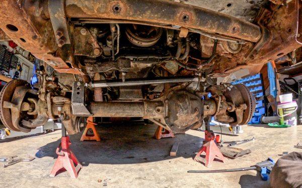
Panhard Bar built and installed
Track bar geometry is critical on any radius-arm Chevy solid axle swap because it directly affects axle centering and suspension movement. The panhard bar prevents side-to-side axle movement while allowing full suspension travel.
Keep the bar as level as possible. A steeper angle increases lateral movement as the suspension cycles.
The frame mount uses 2.65″ spacing for a Johnny Joint. The axle mount uses 2″ spacing for a 3/4″ heim. A 7/8″ heim would be stronger, but this setup works for a budget trail build.
The bar itself is 1.25″ Schedule 40. Larger DOM tubing would be ideal, but this was built from available materials.
You can get these Chevy SAS Panhard brackets over in my shop.
Shock Mounts, Bump Stops, and Limit Straps
These still need final placement, but I’m holding off until the front driveshaft, steering, and wheels are installed so I can fully flex the suspension and measure everything at full bump and droop.
That final mockup will determine the best locations for shock mounts, bump stops, and limit straps, while also letting me check steering, driveshaft, and tire clearance at the same time.
That will be covered in Part 3, along with final welding and first test-drive checks.
Final Notes on Building a Chevy SAS Kit

Major Fabrication Finished!
Overall, the system wasn’t difficult to design or build. CAD and a plasma table make it easier to produce clean, repeatable parts, but everything here could be done with simpler tools.
Frame prep is critical. Clean to bare metal using a wire wheel and flap disc. Good prep results in stronger, cleaner welds.
Continue to Part 3: Final Assembly and Trail Run
In Part 3, we finish up all the mechanical odds and ends.
- Front Driveshaft U-joint
- Steering Links, Pitman Arm and Setup
- Exhaust Relocation around front driveshaft
- Drilling unit bearings to match rear axle
- Gear Ratios and Welding Diffs
- Hooking up brakes, shocks, limiting straps, bumpstops
- Flexing out truck, checking clearances
- Final Welding of all components
- Taking it out for a test run!
If you’re building your own GMT800 Dana 60 swap, make sure to read Part 1, watch the Part 2 video, and check out the complete Chevy SAS kit here.
Safety Disclaimer
Performing a solid axle swap involves cutting, grinding, welding, and supporting heavy loads. Only attempt this work if you are confident in your mechanical and fabrication skills. Always use proper jack stands, wear eye/ear protection, keep fire suppression nearby, and disconnect your battery before cutting or welding.
You are responsible for your own safety and the safety of anyone around you.
Some of the links provided are Amazon Associate affiliate links. I may earn a commission at no extra cost to you.